Basic technical data of capacitors
Basic concept: The plate capacitor
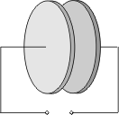
Two metal plates equal in size stand opposite each other a certain distance apart, separated by air or some other insulator. Voltage is applied:
The capacitor takes up both negative and, on the other hand, positive charged carriers on the surface of it's plates. It stores electric charges, so to speak.
(Mechanical analogy: storage receptacle for fluid).
Direct current is normally unable to pass through this structure; due to the insulator (dielectric) lying in between, the electrons cannot get from one plate to the other. This is only possible in the case of very high voltage, and then a breakdown occurs due to ionization.
Note: The capacitor is usually infinitely resistant to direct current (DC).
On the other hand, the capacitor lets alternating current (AC) through. The current cannot flow directly through the dielectric even here, but because of the alternating charging and discharging of the plates, charged carriers appear to be transported through the capacitor. Of course, the capacitor presents some resistance to alternating current too, this is dependent on the frequency.
Note: At lower frequencies the capacitive resistance is higher. At higher frequencies the capacitive resistance is lower.
Dielectric
In reality the dielectric is not an ideal insulator, i.e. a certain number of electrons penetrate it. Due to these processes and also to changing polarization in the material, part of the electric energy is lost as dissipated heat:
a) Ohmic losses: there is a difference between insulation resistance = volume resistance Rv (current flow through the interior of the insulator) and surface resistance = the external resistance Rs (current flow over the surface of the insulator due to humidity or dirt). Together they make up the complete resistance
The ohmic losses are to be seen in the rise of the temperature of the insulator which is often quite considerable.
b) Dielectric losses (dissipation) are the result of the changing polarization of the elementary particles of the dielectric caused by alternating fields. They are transformed into oscillations (like little compass needles) and thus produce frictional heat. So, here too, part of the electric energy is lost in heat.
The losses amount to:
tanδ is the dissipation factor, it is the measurement of dielectric losses and is dependent on frequency.
a) Ohmic losses: there is a difference between insulation resistance = volume resistance Rv (current flow through the interior of the insulator) and surface resistance = the external resistance Rs (current flow over the surface of the insulator due to humidity or dirt). Together they make up the complete resistance
| Rtotal = Ri x RaRi + Ra |
The ohmic losses are to be seen in the rise of the temperature of the insulator which is often quite considerable.
b) Dielectric losses (dissipation) are the result of the changing polarization of the elementary particles of the dielectric caused by alternating fields. They are transformed into oscillations (like little compass needles) and thus produce frictional heat. So, here too, part of the electric energy is lost in heat.
The losses amount to:
| P = Urms2 x 2 x π x f x C x tanδ |
tanδ is the dissipation factor, it is the measurement of dielectric losses and is dependent on frequency.
Capacitance
| Definition: | A capacitor is measured by the size of its capacitance. A capacitance is the electric capacity of a capacitor, i.e. the amount of electrically charged carriers it can store. | |||||
| Symbol: | C | |||||
| Measurement unit: | F = farad |
|||||
| Calculation example: |
The capacitance is 1 farad when a current of 1 ampere flows for one second with the applied voltage of 1 V. |
|||||
Q ~ U
The proportional factor C is the capacitance of the capacitor
Q = C x U
Capacitance calculation for the plate capacitor
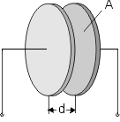
| C = ɛ0 x ɛr x Ad |
| ɛ0 |
= absolute dielectric constant = 0.0885 x 10⁻¹² farad/cm |
| ɛr . | = relative dielectric constant depending on insulation material |
| A | = plate surface (one plate only) in cm2 |
| d | = distance between plates in cm |
The relative dielectric constant can have values between ɛr = 1 (air) and ɛr ~ 10,000 (special ceramic materials).
Capacitance tolerance
Tolerance is the permissible relative deviation of the capacitance from the rated value, expressed in per cent. The tolerance is to be measured at a temperature of +20°C and is only valid at the time of delivery.
After a longer period of storage or use, the tolerance can increase; but, according to standard specification, it may never exceed twice the value measured at the time of delivery.
The following delivery tolerances are usual for wound capacitors:
±1%; ±2.5%; ±5%; ±10%; ±20%.
In the case of electrolytic capacitors for which the largest possible capacitance matters, tolerances of +100/-20% also occur.
Note: The tolerance (with the exception of 20%) is usually clearly marked on the body of the capacitor, in case of very small capacitor sizes, coding or ciphers according to IEC 60062 are also used.
Rated voltage / Voltage derating
Each capacitor is designed for a particular rated voltage, which it must stand up to without adverse effect during continuous operation.
However, this only applies to ambient temperatures of < +85°C; at higher temperatures the maximum permissible voltage or voltage limit for continuous operation is reduced by voltage derating.
This is caused by tiny weak points in the dielectric, which, under increased temperatures, are subject to greater stress and can then break down.
In the case of rated voltage, DC voltage specifications are distinguished from AC voltage data. In general, this information is printed on the capacitor with clear symbols; in the case of capacitors with very small dimensions code symbols may be necessary as with the tolerance specifications.
With all thermoplastic film dielectrics, the voltage strength diminishes when the temperature is increased.
The voltage derating gives the percentage by which the permissible voltage is reduced compared to the rated voltage, for DC voltage operation from +85°C and for AC voltage operation from +75°C, at a temperature increase of 1K.
However, this only applies to ambient temperatures of < +85°C; at higher temperatures the maximum permissible voltage or voltage limit for continuous operation is reduced by voltage derating.
This is caused by tiny weak points in the dielectric, which, under increased temperatures, are subject to greater stress and can then break down.
In the case of rated voltage, DC voltage specifications are distinguished from AC voltage data. In general, this information is printed on the capacitor with clear symbols; in the case of capacitors with very small dimensions code symbols may be necessary as with the tolerance specifications.
Voltage derating:
With all thermoplastic film dielectrics, the voltage strength diminishes when the temperature is increased.
The voltage derating gives the percentage by which the permissible voltage is reduced compared to the rated voltage, for DC voltage operation from +85°C and for AC voltage operation from +75°C, at a temperature increase of 1K.
Insulation resistance
Paper and plastic film capacitors usually have insulation resistance values ranging from 6000 to 12000 MΩ.
The insulation resistance is given in Ohm. This is not quite explicit because the insulation resistance changes for a time after voltage is applied - the self-discharge constant Τ = Ris x C is also used to measure the quality of the insulation.
The time constant gives the time in seconds during which the voltage between the terminating wires of a charged capacitor decreases to 37% due to self-discharging.
With capacitance values in the µF range, the time constant at the time of delivery is usually between 2000 and 4000 seconds.
Humidity which penetrates into the capacitor winding, lowers the insulation resistance. An appropriately thick casing should therefore be provided, according to how much humidity the capacitor will be subjected to.
Good insulation resistance is necessary for capacitors which are used to block off DC voltage and for storage capacitors in which a particular voltage rate has to remain unchanged for a longer period of time.
Dissipation factor and ESR
The dissipation factor tanδ is the quotient of the active and reactive components of the impedance.
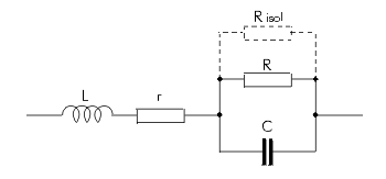
The losses occur mainly in the dielectric and are represented by R in the equivalent circuit diagram.
Parallel to R is the insulation resistance Ris, which, in fact, only affects tanδ at very low frequencies.
Further dissipation is caused by the finite conductivity of the electrodes and the transfer resistance between the electrodes and the terminating wires.
This is represented in the equivalent circuit diagram by the series resistance r.
L represents the remaining self-inductance.
The dissipation factor is, for example, of importance for AC capacitors, which are subjected to strong currents: too high a tan can lead to excessive heating brought about by the incoming active power and thus to a shorter life time.
Values of ESR are not directly stated in the data sheets of plastic film capacitors. The ESR for an individual capacitance value C can be calculated by the formula
ESR = tanδ x (2 x π x f x C)-1
tanδ: see data sheet of the respective WIMA type
f: frequency of the AC voltage share in the application
The losses occur mainly in the dielectric and are represented by R in the equivalent circuit diagram.
Parallel to R is the insulation resistance Ris, which, in fact, only affects tanδ at very low frequencies.
Further dissipation is caused by the finite conductivity of the electrodes and the transfer resistance between the electrodes and the terminating wires.
This is represented in the equivalent circuit diagram by the series resistance r.
L represents the remaining self-inductance.

The dissipation factor is, for example, of importance for AC capacitors, which are subjected to strong currents: too high a tan can lead to excessive heating brought about by the incoming active power and thus to a shorter life time.
ESR (Equivalent Series Resistance)
Values of ESR are not directly stated in the data sheets of plastic film capacitors. The ESR for an individual capacitance value C can be calculated by the formula
ESR = tanδ x (2 x π x f x C)-1
tanδ: see data sheet of the respective WIMA type
f: frequency of the AC voltage share in the application
Inductance and self-resonance
Depending on the construction, an alternating current in the capacitor winding creates a more or less distinctive magnetic field which can be measured as inductance L (see equivalent circuit diagram).

The self-inductance L of modern capacitors - reduced by structural measures (e.g. contact over the end surfaces) - is approximately 10 nH. It is therefore not greater than the inductance of a wire, which is as long as the capacitor pins plus the pin spacing.
L and C form a series oscillating circuit; at a frequency of
the capacitor is in self-resonance and has the lowest impedance, which only consists of r (ESR equivalent series resistance).

The self-inductance L of modern capacitors - reduced by structural measures (e.g. contact over the end surfaces) - is approximately 10 nH. It is therefore not greater than the inductance of a wire, which is as long as the capacitor pins plus the pin spacing.
L and C form a series oscillating circuit; at a frequency of
| f0 = 12π x √L x C |
the capacitor is in self-resonance and has the lowest impedance, which only consists of r (ESR equivalent series resistance).
Temperature coefficient (TKc)
The temperature coefficient α shows the fraction by which the capacitance, measured at +20°C, changes when the surrounding temperature rises by 1 degree C.
C20 = capacitance at +20°C
CT = capacitance at T°C
α can be positive or negative. In the case of good capacitors the TKc is in the region of just a few 10-5/°C.
TKc 10-5/°C = 10 x 10-6/°C = 10 ppm/°C
| CT = C20 x [1 + α x (T - 20° C)] |
C20 = capacitance at +20°C
CT = capacitance at T°C
α can be positive or negative. In the case of good capacitors the TKc is in the region of just a few 10-5/°C.
TKc 10-5/°C = 10 x 10-6/°C = 10 ppm/°C
Pulse stressing
In the case of metallized capacitors the user has to give guidelines for the maximum possible pulse stressing because of the limited current capacity of electrodes and contacts. gegeben werden.
These guidelines are worked out by means of so-called pulse tests, in which the stress which might occur during application, is simulated.
In a test circuit in accordance with IEC 60384 part 1, the test specimen is charged and then discharged intermittently. The test voltage corresponds to the rated DC voltage and the test comprises 10000 pulses with a repetition frequency of 1 Hz.
The pulse stress capacity is given as pulse rise time in V/µsec. The stipulations for individual capacitor series are in accordance with the CECC type specifications. The rated or operational pulse rise time is specified as 1/10 of the test pulse rise time.
The pulse rise time F given in V/µsec is also indirectly the maximum current capacity.
C in µF
I in A
The values on the pulse rise time refer to pulses equal to the full rated voltage, so that, at lower operating voltages the permissible pulse rise times may also be increased.
These guidelines are worked out by means of so-called pulse tests, in which the stress which might occur during application, is simulated.
In a test circuit in accordance with IEC 60384 part 1, the test specimen is charged and then discharged intermittently. The test voltage corresponds to the rated DC voltage and the test comprises 10000 pulses with a repetition frequency of 1 Hz.
The pulse stress capacity is given as pulse rise time in V/µsec. The stipulations for individual capacitor series are in accordance with the CECC type specifications. The rated or operational pulse rise time is specified as 1/10 of the test pulse rise time.
The pulse rise time F given in V/µsec is also indirectly the maximum current capacity.
| I = F x C x 1.6 |
C in µF
I in A
The values on the pulse rise time refer to pulses equal to the full rated voltage, so that, at lower operating voltages the permissible pulse rise times may also be increased.
Long term stability / temporal inconstancy
Environmental influences such as heat, high humidity and strong mechanical vibrations can, over a longer period of time, due to ageing, lead to an irreversible change in the capacitance value.
The information about the temporal inconstancy lays down the maximum extent to which the capacitance of a capacitor may change under the influence of environmental factors.
As a rule, temporal inconstancy is given in %. The period of time specified by the relevant standards is 2 years, based on a regular temperature of +40°C. Changes after two years are virtually of no importance.
Typical values are, for example, ±3% for KT-/MKT capacitors and ±0.5 or ±1% for KP-/MKP capacitors according to type.
Dielectric absorption
A capacitor which has been charged for a long time and then been completely discharged, has a small voltage on its terminal wires again, within seconds or minutes. This effect is known as dielectric absorption.
This phenomenon has a particularly unfavorable effect in sample and hold applications in which charges are to be stored for comparision/measuring purposes.
The recharging comes from polarization processes in the insulating material and is largely independent of the capacitance of the capacitor and the thickness of the dielectric.
The standard MIL-C-19978 describes the measuring method of the dielectric absorption.
Circuit diagram:
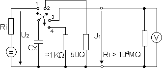
The capacitor Cx is charged for 15 minutes on a reference DC voltage, e.g. up to the rated DC voltage of the capacitor. The initial current surge may not exceed 50 mA. At the end of the charging time the capacitor is separated from the charging source and discharged over a resistance of 50 Ω. The discharging resistance is removed from the capacitor after 10 sec. The "regained voltage" is measured after a period of 15 minutes with a high ohmic (Ri > 10000 MΩ) millivoltmeter.
The dielectric absorption DA can be calculated according to the following formula:
DA = U1 / U2 x 100%
DA = dielectric absorption
U1 = regained voltage
U2 = charged voltage
Typical values of some dielectrics in % at T = +23°C:
This phenomenon has a particularly unfavorable effect in sample and hold applications in which charges are to be stored for comparision/measuring purposes.
The recharging comes from polarization processes in the insulating material and is largely independent of the capacitance of the capacitor and the thickness of the dielectric.
Measuring of Dielectric Absorption
The standard MIL-C-19978 describes the measuring method of the dielectric absorption.
Circuit diagram:

The capacitor Cx is charged for 15 minutes on a reference DC voltage, e.g. up to the rated DC voltage of the capacitor. The initial current surge may not exceed 50 mA. At the end of the charging time the capacitor is separated from the charging source and discharged over a resistance of 50 Ω. The discharging resistance is removed from the capacitor after 10 sec. The "regained voltage" is measured after a period of 15 minutes with a high ohmic (Ri > 10000 MΩ) millivoltmeter.
The dielectric absorption DA can be calculated according to the following formula:
DA = U1 / U2 x 100%
DA = dielectric absorption
U1 = regained voltage
U2 = charged voltage
Typical values of some dielectrics in % at T = +23°C:
| - Polypropylene - Polyester - Mixed dielectric - Ceramic (X7R) - Ceramic (Z5U) |
0.05 ... 0.10 0.20 ... 0.25 0.12 ... 0.18 0.60 ... 1.00 2.00 ... 2.50 |
Reliability
For plastic film capacitors the formula
is valid for the failure rate in fit (10-9/h)
λo = expected value
πT = temperature fakcor
πU = voltage factor
The expected value is determined for each component on the basis of long term tests and field experience. Long term tests refer to a minimum test period of t > 10000 h.
If such a test is carried out at a temperature of 85°C, for example, that would, in an appliance with a surrounding temperature of T < 40°C, correspond to an operating time of 150000 - 200000 hours; a value which comes close to real operating conditions. Due to the element of uncertainty about accuracy of these calculations, a subject which has also been described in technical literature, this value is given with a confidence limit of 60%. However, according to our experience, these values largely correspond to the field results.
Correction factors which are specific to the different applications, result from temperature and/or voltage stress capacity according to the following tables.
λo = 2 fit
πT = 1
πU = 5
λ = 2 x 5 x 1 = 10 fit
The expected values for other types of capacitors are available on request.
| λ = λo x πT x πU |
is valid for the failure rate in fit (10-9/h)
λo = expected value
πT = temperature fakcor
πU = voltage factor
The expected value is determined for each component on the basis of long term tests and field experience. Long term tests refer to a minimum test period of t > 10000 h.
If such a test is carried out at a temperature of 85°C, for example, that would, in an appliance with a surrounding temperature of T < 40°C, correspond to an operating time of 150000 - 200000 hours; a value which comes close to real operating conditions. Due to the element of uncertainty about accuracy of these calculations, a subject which has also been described in technical literature, this value is given with a confidence limit of 60%. However, according to our experience, these values largely correspond to the field results.
Correction factors which are specific to the different applications, result from temperature and/or voltage stress capacity according to the following tables.
Temperature factor πT
| T (°C) | 40 | 50 | 70 | 80 | 100 |
| πT | 1 | 2 | 5 | 10 | 15 |
Voltage factor πU
| U/U |
0.1 | 0.25 | 0.5 | 0.75 | 1.0 |
| πU | 0.2 | 0.3 | 1 | 2 | 5 |
Today metallized plastic film capacitors with Polyester film achieve the best values.
Here the expected value is about 2 fit. This results in a failure rate of 10 fit.
Example: WIMA MKS 2 / 0.1 µF / 63 VDC
λo = 2 fit
πT = 1
πU = 5
λ = 2 x 5 x 1 = 10 fit
The expected values for other types of capacitors are available on request.
Warning notice
AC Voltage Load at the Mains
Anticipating possible interfering pulses, DC voltage capacitors must not be operated at the mains (line power), irrespective of the rated AC voltage. For this purpose, use approved electromagnetic interference suppression capacitors only.
Thermal Load in the Application
If a plastic film capacitor is overstressed due to inappropriate usage under AC voltage conditions, the temperature inside the component may rise to an impermissibly high level. Thus, the dielectric film may subsequently be damaged leading to a short circuit or formation of smoke and even fire in the capacitor. It may also happen if the capacitor is overheated by an external heat source.
Shock and/or Vibration Load for Larger Case Sizes
For increased shock and vibration applications involving larger case sizes (i.e., PCM 22.5 mm pin spacing or greater), it is recommended to fix capacitors in an appropriate way; or special pin and tab terminations may be required respectively, to minimize pin separation from the capacitor element or the solder joint.
Processing
When processing plastic film capacitors it is mandatory to observe the application recommendations with regard to soldering and/or cleaning and drying processes.
General Remarks
All data, range surveys and application data correspond to the actual state of the art and were elaborated as thoroughly and precisely as possible. They are to be understood as general information, and the right for amendments and construction changes is reserved. Special customized designs which deviate from our catalogue data, irrespective of whether being based on factory standards, specifications or related data, do not release the user from his duty of care with regard to incoming goods inspection and production monitoring. In case of the components being purchased through second or third suppliers we urgently ask to compare the technical details with the data given by the manufacturer. In cases of doubt we recommend use is made of our technical support, since we do not take any responsibility for damages caused by inappropriate use or processing of our capacitors.
