Our Attitude – Always at your service
Frequently Asked Questions
WIMA Certificates
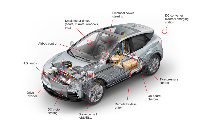
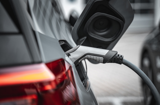
Automotive Applications
Substitution of obsolete polycarbonate (PC) capacitors
However, the question of which capacitors can be used to replace the PC series is still of interest. The following comparisons may be of assistance in making decisions.
The special feature of Polycarbonate (PC) capacitors is the almost constant course of capacitance drift versus temperature and the suitability for special applications in the field of higher frequencies respectively.
 Capacitance change with temperature
 Dissipation factor change with frequency
Substitution by Polyester (PET) Capacitors
 Capacitance change with temperature
Results: In the field of normal application temperature 0/+20 to +80°C Polyester (PET) shows a comparable linearity of the capacitance course in the positive field in comparison with Polycarbonate (PC) which shows a slightly negative course. The capacitance inconstancy versus time is basically identical with both dielectrics.
Substitution suggestions for metallized capacitors:
| Obsolete WIMA type | PCM | Suggested WIMA type | PCM | Replace also obsolete competitor series |
| WIMA MKC 02 | 2.5 | WIMA MKS 02 | 2.5 | |
| WIMA MKC 2 | 5 | WIMA MKS 2 | 5 | MKC 1858 / CMK |
| WIMA MKC 3 | 7.5 | WIMA MKS 4 | 7.5 | CMK |
| WIMA MKC 4 | >10 | WIMA MKS 4 | >10 | MKC 1862 / MKC 344 / CMK |
Substitution suggestions for film/foil capacitors:
| Obsolete WIMA type | PCM | Suggested WIMA type | PCM | Replace also obsolete competitor series |
| WIMA FKC 2 | 5 | WIMA FKS 2 | 5 | KC 1850 / CFR (CMK) |
| WIMA FKC 3 | >7.5 | WIMA FKS 3 | >7.5 | CMK |
Substitution suggestions for Polypropylene (PP) capacitors:
 Capacitance change with temperature
 Dissipation factor change with frequency
Results: in comparison to Polycarbonate (PC), Polypropylene (PP) has a lower dissipation factor throughout the course of the whole temperature field.
Substitution suggestions for metallized capacitors:
| Obsolete WIMA type | PCM | Suggested WIMA type | PCM | Replace also obsolete competitor series |
| WIMA MKC 2 | 5 | WIMA MKP 2 | 5 | MKC 1858 / CMK |
| WIMA MKC 3 | 7.5 | WIMA MKP 4 | 7.5 | CMK |
| WIMA MKC 4 | >10 | WIMA MKP 4 | >10 | MKC 1862 / MKC 344 / CMK |
| WIMA MKC 10 | >7.5 | WIMA MKP 10 | >7.5 |
Substitution suggestions for film/foil capacitors:
| Obsolete WIMA type | PCM | Suggested WIMA type | PCM | Replace also obsolete competitor series |
| WIMA FKC 02 | 2.5 | WIMA FKP 02 | 2.5 | |
| WIMA FKC 2 | 5 | WIMA FKP 2 | 5 | KC 1850 / CFR (CMK) |
| WIMA FKC 3 | >7.5 | WIMA FKP 3 | >7.5 | CMK |
Marking of WIMA capacitors
SMD capacitors
Marking of WIMA SMD capacitors was gradually ceased as of July 2003. Identification is possible by the labelling of packages and delivery notes respectively.
Through-Hole Capacitors
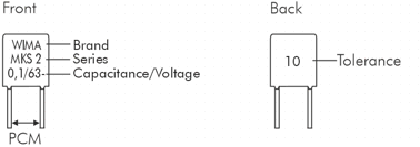
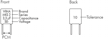
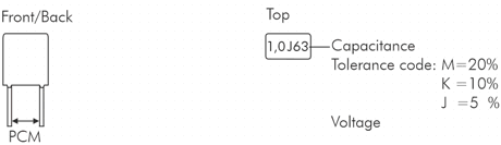
In general, WIMA through-hole capacitors are marked on the front side of the box in plain text with brand name, capacitor series, capacitance, nominal voltage, date code and tolerance. Capacitors with PCM smaller than 15 mm will have the tolerance indicated on the reverse. Standard tolerance 20% is not marked.
PCM 2.5 mm box size < 3.8 x 8.5 x 4.6 mm
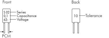
PCM 2.5 mm box size > 3.8 x 8.5 x 4.6 mm
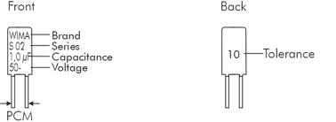
PCM 5 mm box size < 8.5 x 10 x 7.2 mm
PCM 5 mm box size > 8.5 x 10 x 7.2 mm
PCM 5 mm top marking
| Capacitance | Code |
| 0.01 µF 0.015 µF 0.022 µF 0.033 µF 0.047 µF 0.068 µF |
10n 15n 22n 33n 47n 68n |
| 0.1 µF 0.15 µF 0.22 µF 0.33 µF 0.47 µF 0.68 µF |
µ1 µ15 µ22 µ33 µ47 µ68 |
| 1,0 µF 1.5 µF 2.2 µF 3.3 µF 4.7 µF 6.8 µF |
1µ 1µ5 2µ2 3µ3 4µ7 6µ8 |
| 10 µF | 10µ |
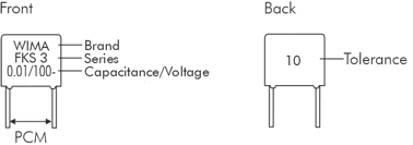
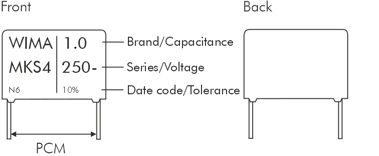
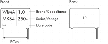
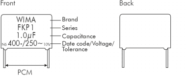


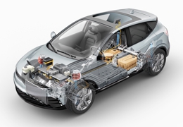


 Figure 1: Schematic representation of the self-healing process
 Figure 2: Isolated area after the self-healing process